Yaskawa 750W ServoPack Servo Drive 200-230VAC 1Phase 11A SGDA-08ASP
Quick Details
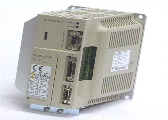
Description SGDA-08ASP is a Drives-AC Servo produced by Yaskawa
Servo Amplifier Type SGDA
Rated Output 750W
Supply Voltage 200V
Model Speed/Torque Control (Analog Input)
Factory setting of applicable motor type SGM Servomotor (blank)
Modification type None
Similar Products
SGDA-01AP
SGDA-01AP+SGM-01A314B
SGDA-01APP
SGDA-01AS
SGDA-01AS+ SGM-01A3NT14
SGDA-01ASY8+SGMP-01AW12
SGDA-01BP
SGDA-01BP+SGMP-01B312
SGDA-01BPY122
SGDA-01BS
SGDA-01VP
SGDA-01VPY197
SGDA-01VS
SGDA-02AP
SGDA-02AS
SGDA-02ASP
SGDA-02BP
SGDA-02BS
SGDA-02VP
SGDA-03BP
SGDA-03BP+SGMP-03B312
SGDA-03BPY122
SGDA-03SP
SGDA-04AH
SGDA-04AP
SGDA-04APP
SGDA-04AS
SGDA-04AS+SGM-04A3NT12
SGDA-04ASP
Ysskawa SGDA Servopack features superior functions and performance. Its compact design allows a volume ratio approximately 1/4 that of the conventional servo amplifier model. The SGDA features an auto-tuning function, JOG operation, various monitoring functions, and a PC monitoring function. It is also compatible with incremental encoders or absolute encoder feedback. The servo amplifier circuit board has been coated with varnish to improve environmental resistance.
Will the power supply source be switched while the VFD is running? This occurs in many buildings, such as hospitals, where loads are switched to standby generators in the event of a power outage. Some drives will ride through a brief power outage while others may not. If your application is of this type, it must be reviewed with the drive manufacturer for a final determination of drive capability.
* Is the load considered hard to start? These are the motors that dim the lights in the building when you hit the start button. Remember, the VFD is limited in the amount of overcurrent it can produce for a given period of time. These applications may require oversizing of the VFD for
higher current demands.
* Are starting or stopping times critical? Some applications may require quick starting or emergency stopping of the load. In either case, high currents will be required of the drive. Again,
oversizing of the VFD maybe required.
* Are external motor disconnects required between the motor and the VFD? Service disconnects at motor loads are very often used for maintenance purposes. Normally, removing a load from a VFD while operating does not pose a problem for the VFD. On the other hand, introducing a load to a VFD by closing a motor disconnect while the VFD is operational can be fatal to the VFD.
When a motor is Started at full voltage, as would happen in this case, high currents are generated, usually about six times the full load amps of the motor current. The VFD would see these high currents as being well beyond its capabilities and would go into a protective trip or fail altogether. A simple solution for this condition is to interlock the VFD run permissive circuit with the service disconnects via an auxiliary contact at the service disconnect. When the disconnect is closed, a permissive run signal restarts the VFD at low voltage and frequency.
* Are there power factor correction capacitors being switched or existing on the intended motor loads? Switching of power factor capacitors usually generates power disturbances in the distribution system. Many VFDs can and will be affected by this. Isolation transformers or line reactors may be required for these applications.
Power factor correction at VFD-powered motor loads is not necessary as the VFD itself does this by using DC internally and then inverting it into an AC output to the motor. All VFD manufacturers warn against installing capacitors at the VFD output.
Variable Frequency Drive Technologies
Three basic types of variable frequency drives offer certain advantages as well as disadvantages
depending on your motor application. The new flux vector drive is also discussed.
While all variable frequency drives (VFDs) control the speed of an AC induction motor by varying the motor's supplied voltage and frequency of power, they all do not use the same designs in doing so. There are three major VFD designs commonly used today: pulse width modulation (PWM), current source inverter
The sketch in Figure 1.2 might suggest that there is a ‘source’ near the top of the bar magnet, from which Xux lines emanate before making their way to a corresponding ‘sink’ at the bottom. However, if we were
to look at the Xux lines inside the magnet, we would Wnd that they were continuous, with no ‘start’ or ‘Wnish’. (In Figure 1.2 the internal Xux lines have been omitted for the sake of clarity, but a very similar Weld pattern is produced by a circular coil of wire carrying a d.c. See Figure 1.6 where the continuity of the Xux lines is clear.). Magnetic Xux lines always form closed paths, as we will see when we look at the ‘magnetic circuit’, and draw a parallel with the electric circuit, in which the current is also a continuous quantity. (There must be a ‘cause’ of the magnetic Xux, of course, and in a permanent magnet this is usually pictured in terms of atomic-level circulating currents within the magnet material. Fortunately, discussion at this physical level is not necessary for ourpurpose.)
Along with showing direction, the Xux plots also convey information about the intensity of the magnetic Weld. To achieve this, we introduce the idea that between every pair of Xux lines (and for a given depth into the paper) there is a same ‘quantity’ of magnetic Xux. Some people have no diYculty with such a concept, while others Wnd that the notion of quanti4
Electric Motors and Drivesfying something so abstract represents a serious intellectual challenge. But
whether the approach seems obvious or not, there is no denying of the practical utility of quantifying the mysterious stuV we call magnetic Xux, and it leads us next to the very important idea of magnetic Xux density (B).
When the Xux lines are close together, the ‘tube’ of Xux is squashed into a smaller space, whereas when the lines are further apart the same tube of Xux has more breathing space. The Xux density (B) is simply the Xux in the ‘tube’ (F) divided by the cross sectional area (A) of thetube, i.e.

OTHER SUPERIOR PRODUCTS
Yasakawa Motor, Driver SG- Mitsubishi Motor HC-,HA-
Westinghouse Modules 1C-,5X- Emerson VE-,KJ-
Honeywell TC-,TK- Fanuc motor A0-
Rosemount transmitter 3051- Yokogawa transmitter EJA-
Contact person: Anna
E-mail: wisdomlongkeji@163.com
Cellphone: +0086-13534205279

 Your message must be between 20-3,000 characters!