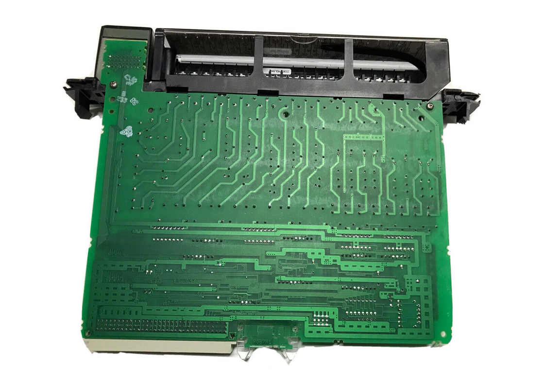
Ge Fanuc IC697MDL940 , Rugged 16-Point Output Relay Module ,120/240 VAC Or 5/24/125 VDC
Product Description
The IC697MDL940 is a rugged 16-point output relay module from the GE Fanuc 90-70 Series that scores highly on both versatility and ease of use. It operates between low and medium power loads such as lamps, contactors, and relays. The module has a rating of 2 Amps per point at a voltage of 120/240 VAC or 24 VDC. It has a current of 0.2 Amps per point for a voltage of 125VDC. The IC697MDL940 module supplies power to energize the relay coils. Each output is fused individually and suppressed with an RC snubber. Be sure to locate the LED indicators at the top of the module. Their role is to indicate the ON-OFF status of each point on the PLC module. For accurate placement with a similar PLC module, the module is mechanically keyed. Its configuration is done using MS-DOS or Windows programming software riding on a platform such as Windows 95 or Windows NT. This is usually done via over the ethernet connection using the TCP/IP protocol. The programming device can range from a personal PC, IBM XT, AT to a PS/2.
For protection, each output is fitted with a 3 Amp fuse which can be replaced with either a fast acting 3AG – 3.0 Amp with a 250 V rating. A 3 Amp 250-volt Metric 5x20mm is also perfectly suitable. The purpose of suppressing each output is to minimize the high frequency noise on the board. Moreover, suppression of the switched load is advised for improved system reliability, lengthening contact life and minimize noise at the control wiring. Each module comes with a mechanical arm for fool proof fitting. This prevents unintentional substitution or swapping of one type of module with another. The field wiring detachable board accepts wire sizes ranging from AWG#22 (0.36mm2) to AWG #14 (2.1mm2). Two wires can be terminated on a single bundle, provided they are of the same size. For this module, there’s plenty of room for routing a bundle of forty #14 wired through the board cavity. The bundle is secured onto the terminal board by a cable tie found at the terminal board’s lower corner.
For best practices during field wiring, ensure you first turn off the power before removal or installation of terminal boards. The jackscrew that secures the terminal board can be accessed upon opening the hinged door. To remove the terminal board from the module, turn the jackscrew in a counter clockwise direction until is it detached. Afterwards, grab the top of the terminal board and thereafter, swing it outwards. The terminal board can accommodate wire sizes ranging from AWG #22 (0.36mm) to AWG #14 (2.10 mm). It’s crucial to note that a maximum insulation diameter of .135 inch should not be exceeded when using AWG #14 (2.10mm) wires. For a perfect connection, two wires can be terminated on any one terminal provided they are of the same size. The design of the terminal board is such that it can only accommodate a maximum of 40 AWG #14 (2.10mm2) wires. To provide ample space for the hinged door to close, they should be placed not less than 8 inches from the end of the termination.
After all connections are completed, the wire bundles are firmly secured by cable ties. A door label is inserted to include wiring information on each module. The terminal board is designed to accept wire sizes from AWG #22 (0.36 mm) through AWG #14 (2.10 mm). It is important that when using AWG #14 (2.10 mm2) wire for wiring all points, that a maximum insulation diameter of .135 inch (3.43mm) not be exceeded. To ensure proper connection, two wires may be terminated on any one terminal only if both wires are the same size. 4. The terminal board is designed to accept a maximum of (40) AWG #14 (2.10 mm2) wires. If AWG #14 (2.10 mm2) wires are to be used, then wire markers should be placed at least 8 inches (203 mm) from termination end to provide sufficient space for the hinged door to close. 6-inch clearance above and below the rack grill is recommended to allow air-flow.
Technical Specifications
| Rated Voltage: |
120/240 VAC or 5/24/125 VDC |
| Number of Outputs: |
16 (8 - Form C and 8 Form A) |
| Max Load Current: |
16 amps per module, 4 amps per group(Form A) |
| Current Required: |
750 mA |
| Freq: |
47-63 Hz (AC only) |
| DC Power: |
Yes |
Technical Information
Specifications
| Relay Type: |
Fixed coil, moving armature |
| Outputs per Module: |
16 |
| Configuration |
8 points - Form C (each point isolated)
8 points - Form A (2 groups with 4 points per group)
|
| Isolation: |
1500 volts - any output to backplane
500 volts between Form C circuits or Form A groups
|
|
Maximum Load Current(Resistive) Per Module
Per Group (Form A)
|
16 amps
4 amps
|
| Output Switching Characteristics |
|
| Nominal Voltage Rating |
120/240 VAC or 5/24/125 VDC |
| Maximum Power |
480 VA (AC loads) or 60 watts (DC loads) |
| Maximum Load Current (resistive) |
2.0 amps from 5 to 265 VAC (maximum), 47-63 Hz |
| |
2.0 amps from 5 to 30 VDC (maximum) |
| |
0.2 amps from 31 to 125 VDC (maximum) |
| |
0.2 amps from 31 to 150 VDC (maximum, Form A only) |
| Minimum Load Current |
10 mA |
| Maximum Output leakage |
1 mA at 120 VAC |
| Response Time-On: |
10 msec (maximum) |
| Response Time-Off: |
10 msec (maximum) |
| Switching Frequency |
20 cycles/minute (inductive load) |
| Contact Type |
Silver alloy |
| Contact Resistance |
0.2 ohm (maximum) |
| Contact Life |
Mechanical: 20 x 106 operations |
| |
Electrical: 105 operations at rated resistive load |
| Protection (each output) |
3 amp fuse |
| |
Snubber (R = 47 ohms, C = 0.015 ïfd) |
| Current Required from 5 V Bus: |
750 mA |
| VME |
System designed to support the VME standard C.1 |


 Your message must be between 20-3,000 characters!