Yaskawa SGMGH-30ACA21 Servo Motor
Industrial NEW Yaskawa ELECTRIC E 23.8A 2900W InsF Servo Motor SGMGH-30ACA21
Product Specifications
| Model | SGMGH-30ACA21 |
| Product Type | AC Servo Motor |
| Rated Output | 2900W |
| Rated Torque | 16.7 Nm |
| Rated Speed | 3000 RPM |
| Power Supply Voltage | 100V AC |
| Rated Current | 23.8 Amps |

Contact Information
Similar Products
SGMGH-03ACB61
SGMGH-03ACB6C
SGMGH-05A2A2B
SGMGH-05A2A61
SGMGH-05A2ASC61
SGMGH-05ACA61 +SGDM-05ADA
SGMGH-05ACA6C
SGMGH-05ACC21
SGMGH-09A2A21
SGMGH-09ACA21
SGMGH-09ACA2B
SGMGH-09ACA2C
SGMGH-09ACA61
SGMGH-09ACA6B
SGMGH-09ACA6C
SGMGH-09ACB61
SGMGH-09ACB6B
SGMGH-09PCA-AM14
SGMGH-12A2B2
SGMGH-12A2B21
SGMGH-13A2A-YR13
SGMGH-13A2A-YR23
SGMGH-13A2A-YR23A
SGMGH-13A2A-YR24
SGMGH-13ACA
SGMGH-13ACA21
SGMGH-13ACA61
SGMGH-13ACA6C
SGMGH-13DCA61
SGMGH-1AACA61
SGMGH-1EACA61
SGMGH-20A2B2C
SGMGH-20ABA6C
SGMGH-20ACA61
SGMGH-20ACA6B
SGMGH-20ACA6C
SGMGH-20ACB2C
SGMGH-20ACB61
SGMGH-20D2A21
Servo Motor Operation Principles
How Servo Motors Work
The gear system within a servomechanism converts the motor's high input speed into a slower, more practical output speed. When the servo motor shaft is at its initial position, the potentiometer generates no electrical signal. This potentiometer output connects to the error detector amplifier. When an external electrical signal is applied to the amplifier's other input terminal, the difference between these signals is amplified and powers the DC motor.
The amplified error signal drives the motor in the desired direction. As the motor shaft rotates, the coupled potentiometer knob also turns via gear arrangement. The changing potentiometer position generates increasing feedback signals. When the motor reaches the desired angular position, the potentiometer signal matches the external signal, eliminating the error signal and stopping the motor.
Gain Effects on Performance
Higher gain reduces the error required to overcome friction or maintain velocity, directly impacting position accuracy and repeatability. The error needed to break static friction can be measured by incrementally changing commands while observing error buildup. Velocity loops significantly influence friction-related errors.
Null hunt—low-frequency back-and-forth movement—occurs when static friction substantially exceeds running friction. This causes overshooting and can be prevented by lowering gain, though this affects accuracy. Reducing the static-to-running friction ratio through roller bearings or specialized coatings (achieving ratios of 1.01 or less) provides better solutions.
Motion accuracy is critical for applications like metal cutting, wood routing, glass etching, and silicon wafer grinding. A servo with 1 IPM/MIL gain exhibits 0.001" error at 1 IPM, 0.01" at 10 IPM, and 0.1" at 100 IPM. Optimal accuracy requires balancing low velocities with high gain.
Servo System Configuration
System Components
- Controlled System: Mechanical system requiring position or speed control, including torque transmission drive systems
- Servomotor: Main actuator moving the controlled system (AC or DC types available)
- Detector: Position or speed detection, typically using motor-mounted encoders
- Servo Amplifier: Processes error signals to correct reference/feedback differences and operate the servomotor
- Host Controller: Controls servo amplifier by specifying position or speed set points
Drive System Components
The controlled system typically involves a movable table driven by ball screws connected to the servomotor via gears. This configuration allows flexible power transmission ratios and high positioning accuracy, though gear play must be minimized.
Alternative drive systems include:
- Coupling + Ball Screw: Ideal for 1:1 power transmission ratios with no play, widely used in machining tools
- Timing Belt + Trapezoidal Screw Thread: Provides flexible ratios without play, though trapezoidal threads offer lower positioning accuracy
For optimal servo system performance, select rigid drive systems with minimal play and configure according to specific control requirements.

 Your message must be between 20-3,000 characters!
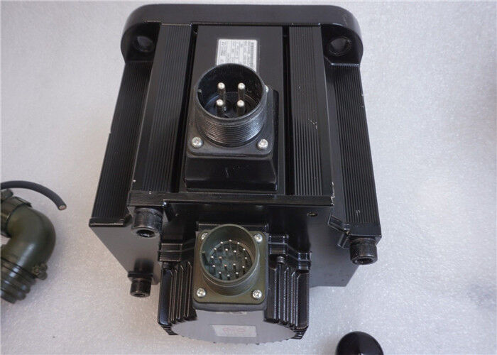
Overall Rating
Rating Snapshot
The following is the distribution of all ratingsAll Reviews