Yaskawa 100W Motors-AC 3000RMP Servo SGM-02L3B4L Industrial Servo Motor
SPECIFITIONS
Current: 0.89A
Volatge: 200V
Power :100W
Rated Torque: 0.318-m
Max speed: 3000rpm
Encoder: 17bit Absolute encoder
Load Inertia JL kg¡m2¢ 10−4: 0.026
Shaft: straight without key
When a current, I, pass through a coil, it induces a magnetic field with two poles (north and south) in this coil. The generated magnetic field H is proportional to the current I. The magnetic field H has a sinusoidal spatial distribution characteristic, and inverts polarity each half period of 180°e. Thus, three magnetic fields, HA, HB, and B HC, are generated when the three phase stator current, IA, IBB, and IC, are applied to the stator windings. The 120ºe phase-shift of the three phase stator currents yield a 120ºe phaseshift on the three magnetic fields, HA, HB, and B HC. The path of these magnetic fluxes is through the rotor and the stator laminations.
The resulting magnetic field at each time instant is equivalent to the sum of the magnetic fields, HA, HBB, and HC, at that specific time instant. The resulting magnetic field rotates as shown in Fig. 2.5. The time instant one (1) of the three phase stator current shown in Fig. 2.5 yields a maximum magnetic field HA due to the peak value of phase current A, and a magnetic field HB and B HC with amplitude equal to a half of the maximum value. The resulting magnetic field for this time instant has the direction of HA. In a similar manner, this same process is repeated for the other time instants two (2) though six (6), yielding a synchronously rotating magnetic field with constant peak amplitude. Thus, this rotating magnetic field generated by the three phase currents applied to the stator windings induces electrical currents in the rotor bars, when the magnetic flux from the stator cuts across the rotor bars.
Similar Products
| SGM-01A312 |
| SGM-01A312C |
| SGM-01A314 |
| SGM-01A314B |
| SGM-01A314C |
| SGM-01A314P |
| SGM-01A3FJ91 |
| SGM-01A3G26 |
| SGM-01A3G36 |
| SGM-01A3G46 SGM-A5A314-Y1 |
| SGM-01A3MA12 |
| SGM-01A3NT14 |
| SGM-01A3NT23 |
| SGM-01A3SO11 |
| SGM-01A3SU11 |
| SGM-01A3SU31 |
| SGM-01A3T012 |
| SGM-01A3TE21 |
| SGM-01ASO11 |
| SGM-01B312 |
| SGM-01B3FJ11 |
| SGM-01B3FJ12 |
| SGM-01L314 |
| SGM-01L314P |
| SGM-01U312 |
| SGM-01U3AP01 |
| SGM-01U3B4L |
| SGM-01V314 |
| SGM-02A312 |
| SGM-02A312B |
| SGM-02A312C |
| SGM-02A312-Y1 |
| SGM-02A314 |
| SGM-02A314B |
| SGM-02A314C |
| SGM-02A3B4SPL |
| SGM-02A3F J73 |
| SGM-02A3G16 |
| SGM-02A3G16B |
| SGM-02A3G24 |
| SGM-02A3G26 |
| SGM-02A3G46 |
| SGM-02A3G46 |
| SGM-02A3MA31 |
| SGM-02A3NT11 |
| SGM-02A3NT12 |
| SGM-02A3SB12 |
| SGM-02A3SN11 |
| SGM-02A3SU12 |
| SGM-02A3TQ11 |
These rotor currents generate a magnetic field on the rotor with opposite polarity in relation to the stator. Since opposite poles attract, the rotor follows the rotating magnetic field of the stator resulting in a rotation of the rotor slightly slower than the rotating magnetic field of the stator. This difference in rotational speed between the rotating fields of the stator and rotor bars is called the slip speed, which will be discussed next in this chapter. In order to produce the required torque, only a small slip speed is required to produce the necessary rotor current due to the small resistance of the shorted rotor bars [40]. Thus, the rotor develops a torque proportional to the product of the stator and rotor currents.

OTHER SUPERIOR PRODUCTS
Yasakawa Motor, Driver SG- Mitsubishi Motor HC-,HA-
Westinghouse Modules 1C-,5X- Emerson VE-,KJ-
Honeywell TC-,TK- Fanuc motor A0-
Rosemount transmitter 3051- Yokogawa transmitter EJA-
Contact person: Anna
E-mail: wisdomlongkeji@163.com
Cellphone: +0086-13534205279

 Your message must be between 20-3,000 characters!
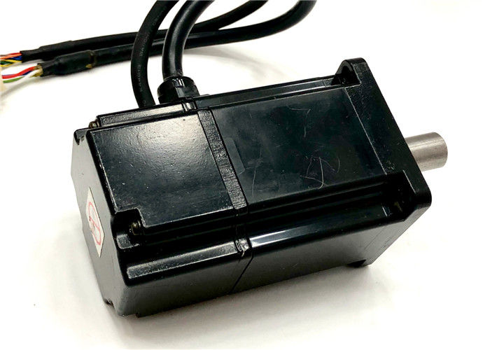
Overall Rating
Rating Snapshot
The following is the distribution of all ratingsAll Reviews